Cross
This example computes light propagation of incident plane waves (at oblique angle of incidence) through an isolated cross:

Cross geometry
Note
As the geometry of this setup exhibits two mirror symmetries the computational domain is reduced to a quarter domain (at higher numerical efficiency).
In a first post process, the Fourier transform for the upper half space is computed (output file transmitted_fourier_transform.jcm). In a subsequent post-process OpticalImaging this Fourier transform is mapped to image_fourier_transform.jcm modelling the light transfer through the optical system (as defined in the post-process OpticalImaging). You can use a Cartesian export post-process to compute the so formed coherent image. The following figure shows the image in different  -slices (image planes displaced along -direction), for
  -polarized illumination.
The following figure shows the image in different -slices (image planes displaced along -direction), for -polarized illumination.
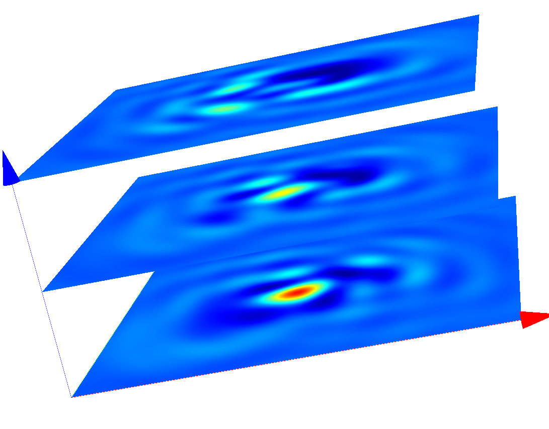
Coherent images of the cross after passing the optical system (s-polarized incoming plane wave with oblique incidence)
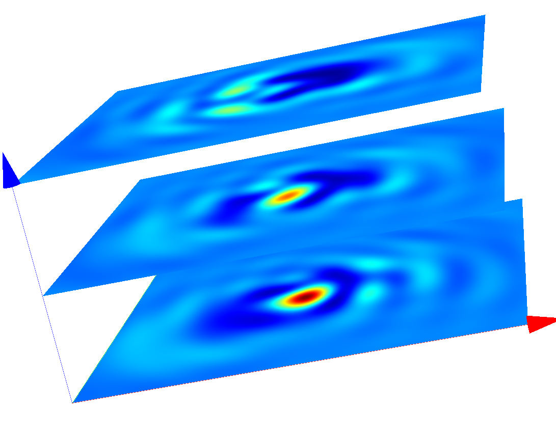
Coherent images of the cross after passing the optical system (p-polarized incoming plane wave with oblique incidence)