Sidewall Angles
Learning targets
- Define 3D objects with non-rectangular sidewalls in z-direction
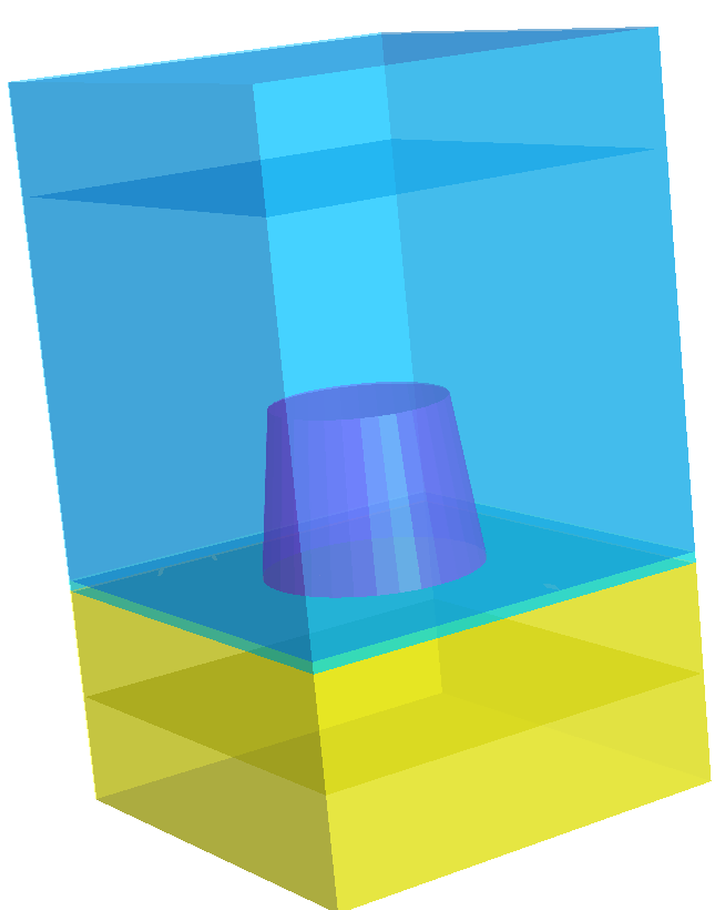
In the previous section we were only able to produce geometries with straight sidewalls in the vertical direction. This example shows how to define non-rectangular sidewalls for the cylinder geometry of the previous section:
As a simple concept we redefine the geometry parameters of the cross-section layout at an interface of two layers. This is done by adding a LayerInterface section between two layers containing a dictionary called GeometryValues:
LayerInterface {
  GeometryValues = [
    Circle/Radius = 0.8
  ]
}
.jcm Input File
layout.jcm [ASCII]
 1
 2
 3
 4
 5
 6
 7
 8
 9
10
11
12
13
14
15
16
17
18
19
20
21
22
23
24
25
26
27
28
29
30
31
32
33
34
35
36
37
38
39
40
41
42
43
44
45
46
47
48
49
50
51
52
53
54
55
56
57
58
59
60
61
62
Layout3D {
  Name = "TutorialExample3D"
  UnitOfLength = 1e-06
  MeshOptions {
    MaximumSideLength = 1.3
  }
  BoundaryConditions {
    Boundary {
      Direction = Vertical
      Class = Transparent
    }
    Boundary {
      Direction = Horizontal
      Class = Periodic
    }
  }
  Extrusion {
    Objects {
      Polygon {
        Name = "ComputationalDomain/Background"
        DomainId = 1
        Priority = -1
        Points = [-2 -2, 2 -2, 2 2, -2 2]
      }

      Circle {
        Name = "Circle"
        DomainId = 2
        Radius = 1
        RefineAll = 2
      }
    }
    MultiLayer {

      Layer {
        Thickness = 1.0
        DomainId = 1
      }
      Layer {
        Thickness = 0.1
        DomainId = 2
      }
      LayerInterface {
        GlobalZ = 0.0
      }
      Layer {
        Thickness = 1.5
        DomainIdMapping = [1 2
                           2 3]
      }
      LayerInterface {
        GeometryValues = [
        Circle/Radius = 0.8
        ]
      }
      Layer {
        Thickness = 2.0
        DomainIdMapping = [1 3]
      }
    }
  }
}
