The Finite-Element Method (FEM) for Nano-Optics Simulations¶ Jupyter Notebook
The software JCMsuite employs the finite element method (FEM) in order to simulate the electrodynamic, mechanic and thermodynamic behavior of nano-optical systems. In this blog we want to motivate and describe the usage of FEM for determining the electrodynamic system properties. We will compare the method to other common approaches like the rigorous coupled-wave analysis (RCWA) and the finite difference time domain (FDTD). Finally, we will present some benchmarks to show that FEM can be orders of magnitude faster and more precise than alternative methods.
Maxwell equations in frequency domain
The behavior of nano-optical systems can in general not be described by ray optics. In order to resolve wave optics phenomena like diffraction, optical resonances, and interference, the full Maxwell equations in matter have to be solved, that describe the behavior of the full electric field $\mathbf{E}$ and the magnetic field $\mathbf{H}$. The Maxwell equations can be solved either in the time domain or in the frequency domain.
In many cases the photonic structures are excited by a time harmonic source (e.g. laser light) or a superposition of time harmonic sources (e.g. sunlight). Even sources emitting "pulses" of single photons can be regarded as time-harmonic. For example, a solid-state quantum dot (QD) can be modeled as a damped oscillating dipole moment $\mathbf{\mu}(t) = {\rm Re}\left\{\mathbf{p} e^{i\omega t}e^{-\gamma t/2}\right\}$. Typically, the frequency $\omega$ is in the regime of a few hundred terahertz while the decay rate $\gamma$ is only on the gigahertz scale. Hence, over many oscillations, the decay can be neglected and the dipole is oscillating harmonically. Hence, the field solution is also time-harmonic and the electric and magnetic fields can be expressed as $\mathbf{E}(\mathbf{r},t) = {\rm Re}\{\mathbf{E}(\mathbf{r},\omega) e^{i\omega t}\}$ and $\mathbf{H}(\mathbf{r},t) = {\rm Re}\{\mathbf{H}(\mathbf{r},\omega) e^{i\omega t}\}$.
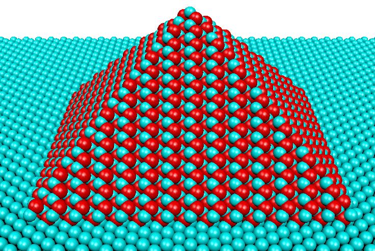 Idealized pyramid-shaped quantum dot. Image by Alexander Kleinsorge used in original form under the CC BY-SA license.
In the case of time-harmonic sources it is much more efficient to solve the Maxwell equations in the frequency domain. The Maxwell equations in the frequency domain read
\begin{eqnarray} \nabla\times \mathbf{E}(\mathbf{r},\omega) & = & i \omega\, \mu(\mathbf{r},\omega)\cdot \mathbf{H}(\mathbf{r},\omega), \\ \nabla\times \mathbf{H}(\mathbf{r},\omega) & = & - i \omega\, \varepsilon(\mathbf{r},\omega)\cdot \mathbf{E}(\mathbf{r},\omega)+\mathbf{J}(\mathbf{r},\omega), \\ \nabla \left[\mu(\mathbf{r},\omega)\cdot \mathbf{H}(\mathbf{r},\omega)\right] & = & 0, \\ \nabla \left[\varepsilon(\mathbf{r},\omega)\cdot \mathbf{E}(\mathbf{r},\omega)\right] & = & \rho(\mathbf{r},\omega). \end{eqnarray}Here, $\mathbf{J}(\mathbf{r},\omega)$ and $\rho(\mathbf{r},\omega)$ are the macroscopically free current and charge distributions. The macroscopic medium is characterized by the spatially dependent permittivity distribution $\mathbf{\varepsilon}(\mathbf{r}, \omega)$ and the permeability distribution $\mathbf{\mu}(\mathbf{r}, \omega)$. In the following, we will omit the dependence on the spatial and frequency coordinates $(\mathbf{r},\omega)$.
When splitting the electric current into the ohmic current and the impressed current, that is $\mathbf{J} = \mathbf{J}^{\mathrm{(Ohm)}}+\mathbf{J}^{\mathrm{(imp)}} = \sigma \mathbf{E}+\mathbf{J}^{\mathrm{(imp)}}$, the second Maxwell equation reads as
\begin{eqnarray} \nabla \times \mathbf{H} & = & - i \omega \mathbf{\varepsilon}_{\mathrm{C}} \mathbf{E}+\mathbf{J}^{\mathrm{(imp)}}, \end{eqnarray}with the complex permittivity tensor
\begin{eqnarray} \mathbf{\varepsilon}_{\mathrm{C}} = \mathbf{\varepsilon}+\frac{i}{\omega}\sigma. \end{eqnarray}In the context of time-harmonic problems the index ‘$\mathrm{C}$’ will be dropped and it should be kept in mind that the permittivity tensor is allowed to have complex-valued entries. From this one obtains independent equations of second order for the electric and magnetic fields:
\begin{eqnarray} \nabla \times \mu^{-1} \nabla \times \mathbf{E} - \omega^2 \mathbf{\varepsilon}\cdot \mathbf{E} & = & i \omega \mathbf{J}^{\mathrm{(imp)}},\\\nabla \times \varepsilon^{-1} \nabla \times \mathbf{H} - \omega^2 \mu\cdot \mathbf{H} & = & \nabla \times \varepsilon^{-1} \mathbf{J}^{\mathrm{(imp)}}. \end{eqnarray}Since the equations are linear, also sources that are not time harmonic can be treated by expanding the fields in a coherent or incoherent superposition of time-harmonic solutions of the Maxwell equations.
As an example, let us consider an add-drop multiplexer. It has four ports that are connected to waveguides. A waveguide mode travelling along the through port impresses a current $\mathbf{J}^{({\rm imp})}$ and is partly outcoupled at the drop port.
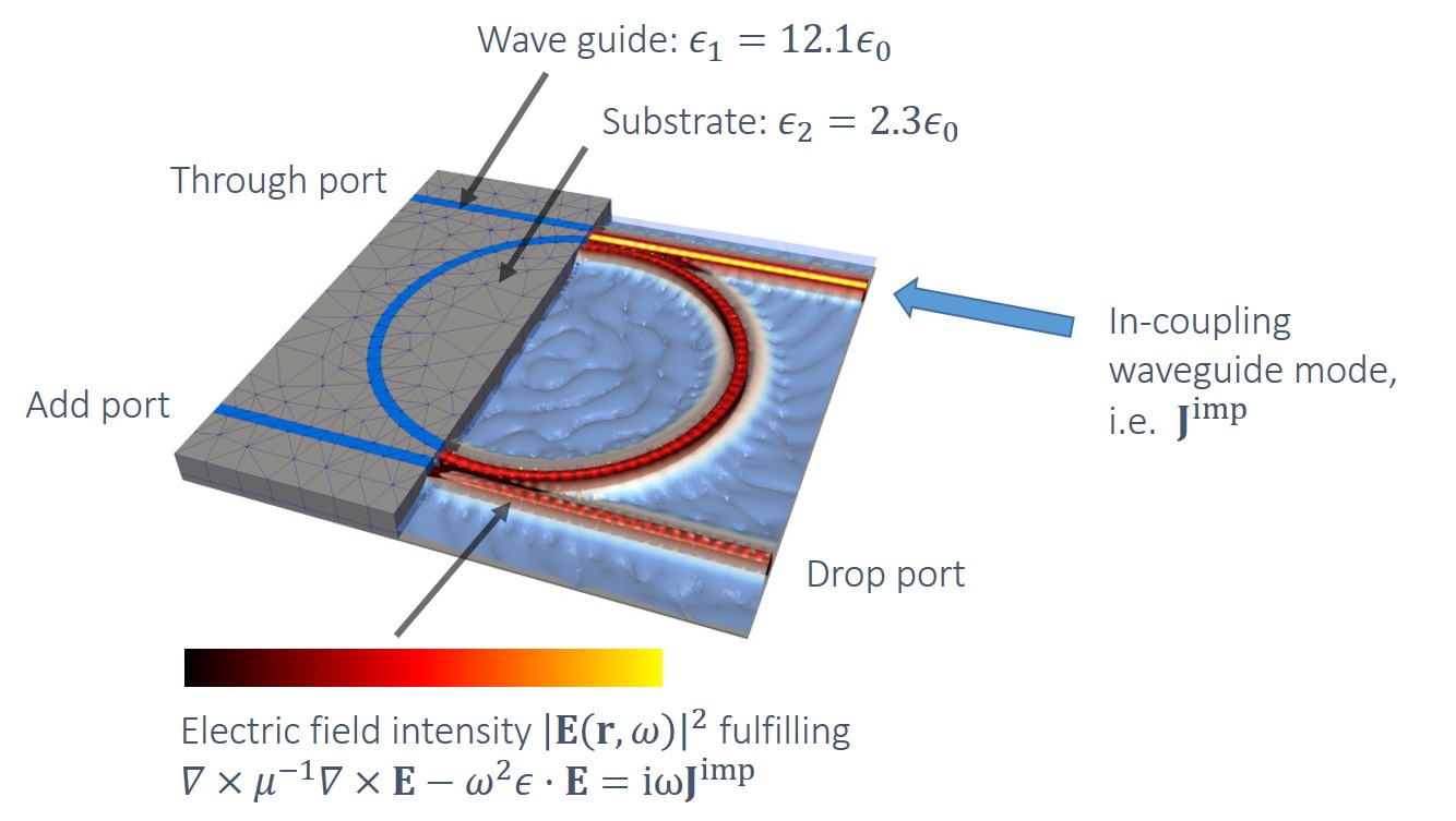
The geometry is defined by a spatially dependent permittivity $\varepsilon(\mathbf{r})$ that equals $12.1\varepsilon_0$ within the waveguides and $2.3\varepsilon_0$ in the substrate. Since waveguide and substrate are non-conductive, the permittivity has no imaginary part.
Finite element approach to solve the Maxwell equations
The recipe of the finite element method
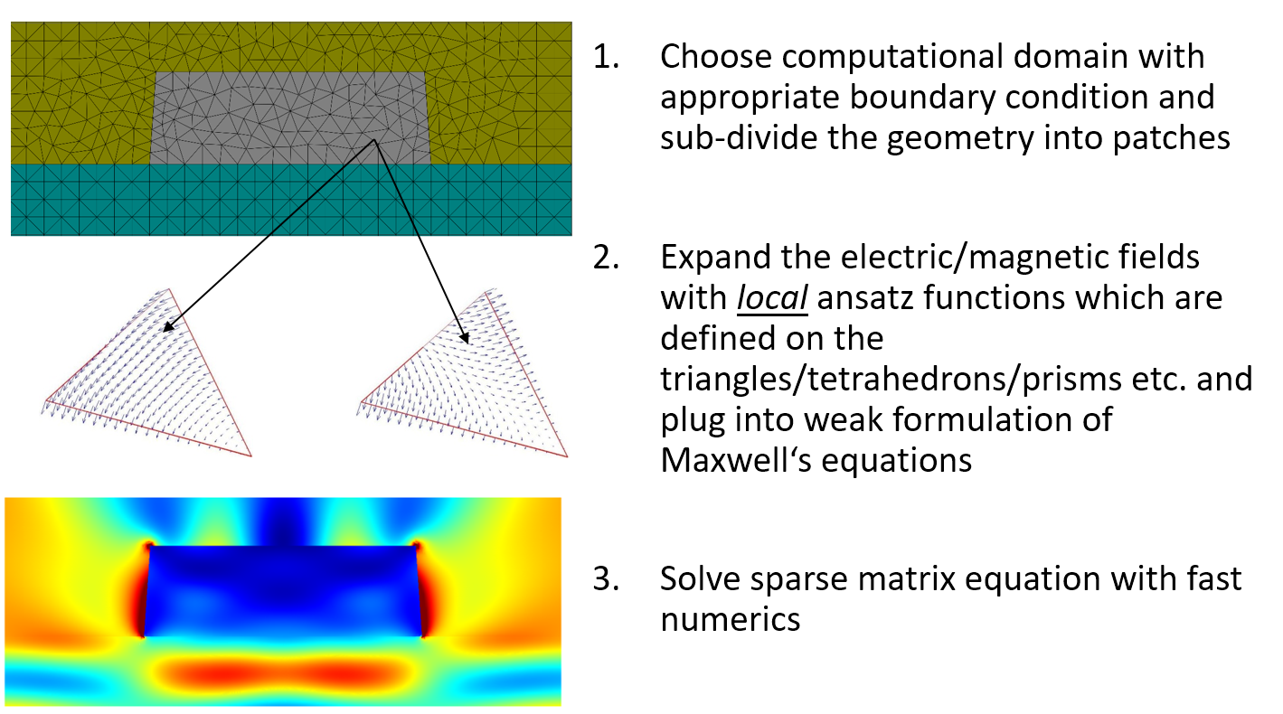
The considered computational domain $\Omega$ is split into subdomains $\Omega_1,\cdots,\Omega_m$ with $\Omega = \bigcup_{i=1}^m \Omega_i$. These domains can be, e.g., triangles for 2D domains and thetraedrons or prisms for 3D domains. The add-drop multiplexer is for example expanded into triangular prisms (see image above).
Within the computational domain, the electric field $\mathbf{E}: \Omega \rightarrow \mathbb{R}^3$ is expanded into ansatz functions $\psi_1,\dots,\psi_n: \Omega \rightarrow \mathbb{R}^3$. The ansatz functions are only non-zero on a small set of neighboring subdomains.
To find a solution of the Maxwell equations, a weak formulation of the problem is regarded. For simplicity, let us consider the Poisson problem for a scalar field $u(\mathbf{r})$. \begin{eqnarray} -\Delta u(\mathbf{r}) &=& f(\mathbf{r})\;\forall \mathbf{r}\in\Omega\\ u(\mathbf{r}) &=& 0\;\forall \mathbf{r}\in\partial\Omega. \end{eqnarray}
Multiplying from the right by a sufficiently smooth test function $\psi$ and integrating yields $$ -\int_{\Omega}\Delta u\, \psi\,{\rm d}^3\mathbf{r} = \int_{\Omega}f\,\psi\,{\rm d}^3\mathbf{r}.$$ An integration by parts gives $$\int_{\Omega}\nabla u \cdot \nabla \psi\,{\rm d}^3\mathbf{r} = \int_{\Omega}f\,\psi\,{\rm d}^3\mathbf{r}.$$
The solution $u$ must fulfill the integral equation for arbitrary test functions $\psi$. Expanding the solution as a weighted sum of basis functions $u = \sum_i c_i \psi_i$ and testing only against every basis function (hence, weak formulation) then yields a system of linear equations for the coefficients $c_i$ $$\sum_i c_i \int_{\Omega}\nabla \psi_i \cdot \nabla \psi_j\,{\rm d}^3\mathbf{r} = \int_{\Omega}f\,\psi_j\,{\rm d}^3\mathbf{r} \; \forall j=1,\dots, n.$$
If we define the system matrix $A$ with the elements $a_{ij} = \int_{\Omega}\nabla \psi_i \cdot \nabla \psi_j\,{\rm d}^3\mathbf{r}$ and a vector $\mathbf v$ with entries $v_i = \int_{\Omega}f\,\psi_j\,{\rm d}^3\mathbf{r}$, then the solution vector $\mathbf{c} = [c_1,\dots,c_n]^T$ evaluates to $$ \mathbf{c} = A^{-1} \mathbf{v}.$$
Because each element is connected to only a few neighboring elements, most of the entries of the system matrix are zero. That is, $A$ is a sparse matrix and it therefore typically inverted with a specialized sparse matrix solver.
Example for a FEM solution using Python, numpy and scipy
The following Python code demonstrates the finite element method for solving the Poisson problem with $\Omega$ beeing a rouded triangle and $f(x,y) = 1$. First, we subdivide the computational domain in triangular patches.
import numpy as np
from scipy.spatial import Delaunay
import matplotlib.pyplot as plt
%matplotlib inline

#Angle-dependent radius of boundary Omega
def r_boundary(angle): return 1+0.12*np.sin(3*angle)

slc = 0.15 #side length constraint for triangulation
radii = np.linspace(slc, 1, int(1/slc));
points = np.array([[0.0,0.0]]);# start with central point
for r in radii:
    n = np.ceil(2*np.pi*r/slc) #number of points on radius
    angles = 2*np.pi*np.arange(n)/n
    r_shape = r*r_boundary(angles)
    x,y = r_shape*np.cos(angles), r_shape*np.sin(angles)
    points = np.concatenate((points,np.column_stack((x,y))))

# Make Delauney triangulation of mesh points
tri = Delaunay(points)

# Last n points are at boundary, others are inner points
is_inner = np.arange(len(points)) < len(points)-n
mask_inner = np.where(is_inner)[0]

# Plot triangulation
fig = plt.figure(figsize=(5,5))
plt.triplot(points[:,0], points[:,1], tri.simplices)
plt.title('Triangulation of computational domain')
plt.show()
Next, we define the basis functions as piecewise linear functions, that form a kind of tent at each node. With the help of the basis we then determine the system matrix $A$ and the right-hand side $\mathbf{v}$. Finally, the solution vector is computed as $\mathbf{c} = A^{-1}\mathbf{v}$.
from scipy.interpolate import LinearNDInterpolator
from scipy.optimize import approx_fprime
from scipy.linalg import solve
from mpl_toolkits.mplot3d import Axes3D

# The basis consists of piecewise linear functions.
# At inner node k it holds psi_k(p_k) = 1 and otherwise psi_k(p_k') = 0
psi = [LinearNDInterpolator(points, values) for values in np.eye(len(points))]

# Gradients of basis functions
def grad_psi(x,y,k):
    return approx_fprime([x,y], psi[k],epsilon=1e-6)

# System matrix defined for basis functions belonging to inner nodes
# Note that all these basis functions go to zero at the boundary.
A = np.zeros((len(mask_inner),len(mask_inner)))
# Right-hand side for f(x,y) = 1
v = np.zeros(len(mask_inner))

for simplex in tri.simplices:
    coords = np.array([points[p] for p in simplex])
    #center of simplex
    c = np.sum(coords,axis=0)/3
    #area of simplex
    a = 0.5*np.linalg.det(np.vstack((coords.T,np.ones(3))))
    for k1 in simplex:
        if not is_inner[k1]: continue
        # the integral of the basis function over the simplex is equal
        # to the volume of a three sided pyramid of height 1
        v[k1] += a/3
        for k2 in simplex:
            if not is_inner[k2]: continue
            # The gradient is constant over the simplex. Hence, we can
            # multiply the integrand value in the center of the simplex
            # times the area of the simplex
            A[k1,k2] += a * grad_psi(*c,k1).dot(grad_psi(*c,k2))

# Solution vector c such that u(x,y) = sum_i c_i psi_i(x,y)
c = np.zeros(len(points))
# at inner points c = A^-1 v
c[mask_inner] = solve(A,v)

# ==== Plot results ====
fig = plt.figure(figsize=(12,4),dpi=150)
ax1 = fig.add_subplot(1,2,1)
ax2 = fig.add_subplot(1,2,2, projection='3d')
cntr = ax1.matshow(A,cmap="RdBu_r")
fig.colorbar(cntr, ax=ax1)
ax2.plot_trisurf(points[:,0], points[:,1], c, triangles=tri.simplices, edgecolor='black')
ax1.set_title('Sparse system matrix A', y=1.08)
ax2.set_title('Solution u(x,y)', y=1.08)
plt.show()
Other numerical approaches to solve the Maxwell equations
Rigorous coupled-wave analysis (RCWA)
RCWA, also called the Fourier Modal Method (FMM), is typically applied to solve the scattering of electromagnetic fields from periodic dielectric structures. The periodic geometry is divided into layers that are uniform in the $z$ direction. Within each layer the solutions can be formulated as a sum of Bloch-periodic waves. The overall problem is then solved by matching boundary conditions at each of the interfaces between the layers.
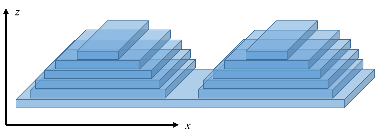 Division of a periodic grating into layers for RCWA. In $x$ direction the filed is expanded into Bloch waves within each layer. In $z$ direction the solutions within each layer are analytically matched.
The method is suited for relatively simple geometries and low index contrasts. For complex geometries, e.g. curved gratings, a large number of layers is required to resolve the shape, leading to a staircase structure. For large index contrast or in the presence of metals, jumps of the electric field cannot be well resolved by the Bloch-periodic basis functions.
Finite-difference time-domain (FDTD)
The Maxwell equations in time domain
\begin{eqnarray} \nabla\times \mathbf{E} & = & -\partial_t\, \mu\cdot \mathbf{H}, \\ \nabla\times \mathbf{H} & = & \partial_t\, \varepsilon\cdot \mathbf{E}+\mathbf{J}(\mathbf{r},\omega), \\ \nabla \left[\mu\cdot \mathbf{H}\right] & = & 0, \\ \nabla \left[\varepsilon\cdot \mathbf{E}\right] & = & \rho \end{eqnarray}describe the time evolution of the electric and magnetic fields. The change of the electric field over time is determined by the spatial change of the magnetic field, and the change of the magnetic field over time is determined by the spatial change of the electric field.
In the FDTD method, the space is discretized with the help of a special grid (Yee grid). At the grid points, the value of the electric and magnetic field strength $\mathbf{E}$ and $\mathbf{H}$ are stored at one point in time. At each grid point, the new $\mathbf{E}$ field and the new $\mathbf{H}$ field for the next point in time are determined alternately. The change of the $\mathbf{E}$-field is calculated from the numerical rotation of the adjacent $\mathbf{H}$-field. The change of the $\mathbf{H}$-field in turn, is calculated from the rotation of the adjacent $\mathbf{E}$-field.
Advantages of the finite element method
In contrast to RCWA and FDTD, the FEM approach allows to decompose the nanophotonic structure in an irregular grid. This can be of great advantage if the structure consists of both large and small features, if rounded structures are considered, or if metallic structures lead to strong field enhancements. In homogeneous regions, relatively large finite elements can be used, whereas at material boundaries, the elements can be chosen smaller to resolve their shape. This approach reduces the size of the system matrix $A$ and thus drastically reduces the computation time.
Another advantage of FEM is that it is not only possible to adapt the size $h$ of the patches but also the number of local basis functions, i.e. the maximal polynomial degree $p$ on each patch. Combining adaptively $h$ and $p$ refinements (hp-FEM) leads leads to a superior convergence. For details, see I. Babuška and B. Q. Guo. "The h, p and hp version of the finite element method; basis theory and applications." Advances in Engineering Software 15 159 (1992).


A benchmark between FEM, RCWA, and FDTD
Each of the methods, FEM, RCWA, and FDTD, has their advantages and limitations. For example, RCWA is working well for periodic structures with a low index contrast where the employed Bloch-periodic basis functions form a very good basis. FDTD is especially suited for illuminations with a very large frequency spectrum. In comparison to FEM it enables also for the treatment of very large computational domains. The FEM system matrix $A$ is most efficiently inverted on a single computer and therefore has to fit into the memory. FDTD, on the other hand, allows for a better parallelization of the computation on several computing nodes. Within FEM very large systems have to be treated with a more complex domain decomposition.
For many real-world problems, we find that FEM provides a very efficient approach to determine the field solutions with high accuracy. As an example, we consider a line grating with a refractive index of $n_{\rm line} = 2.52 + 0.596i$ on a SiO$_2$ substrate ($n_{\rm subs} = 1.56306$).
 Schematics of the geometry of a periodic line mask: The computational domain consists of a line on a substrate material surrounded by air. The geometry is periodic in $x$-direction and it is invariant in $y$-direction.
 The figure below compares the computation times for different numerical resolutions of the line grating using FEM, RCWA, and FDTD. Since the computations were carried out on different platforms, the computation time is given in units of a Matlab FFT run on the same platform. One unit of time corresponds to approx. 0.25 seconds. As one can see, depending on the computational effort, FEM can be many orders of magnitude more accurate than the other methods. Even if one is interested in a moderate accuracy of, say, 1% it is beneficial to use FEM since the computation time for this accuracy is more than an order of magnitude faster than that of RCWA and FDTD.
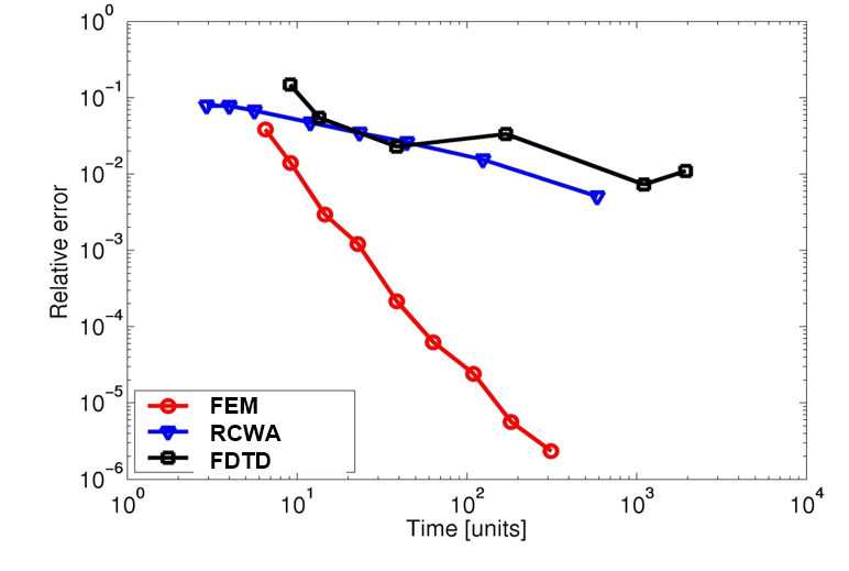 Relative error of the zeroth complex Fourier coefficient vs. the normalized computation time for incoming TE-polarized light.
For more details on this benchmark, see S. Burger et al. "Benchmark of FEM, waveguide, and FDTD algorithms for rigorous mask simulation." 25th annual BACUS Symposium on photomask technology. Vol. 5992 (2005).
Other FEM implementations
The efficiency of the finite element method can strongly depend on the specific implementation. For example, the way in which a geometry is subdivided into patches plays an important role for the final performance and accuracy of the computation. In a collaboration between different research groups in China, France, The Netherlands, and Germany several solvers for computing the quasi-normal modes of nanophotonic resonators with dispersive media have been considered. For details, see P. Lalanne et al. "Quasinormal mode solvers for resonators with dispersive materials." JOSA A 36.4 686 (2019).
As a part of this work, the FEM solver of JCMsuite is compared with other commercial and non-commercial FEM-solvers (see reference for a detailed description). The considered benchmark problem consists of determining the complex eigenfrequencies of the modes of a 2D plasmonic crystal composed of a periodic array of metallic squares in air.
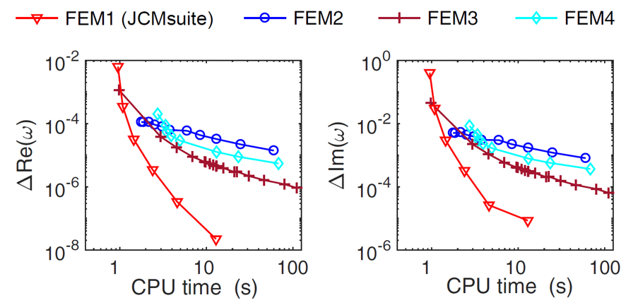 Relative error of the real and imaginary part of the complex eigenfrequency as a function of the CPU time.
 Conclusion
The finite-element method (FEM) is a powerful numerical approach for the efficient electromagnetic field simulation. The discretization of the geometries into flexible unstructured meshes has important advantages over alternative approaches like RCWA and FDTD. The shape of complex structures can be well resolved while keeping the numerical costs relatively small. Also metallic structures can be simulated with high precision.
The JCMsuite uses the finite-element method for the efficient simulation of photonic structures. To assess the performance of the software for your system of interest, you can download a free trial version. The Electromagnetics Tutorial contains simulation examples from many application fields, such as computational lithography, computational metrology, waveguides and fibers, photovoltaics, light sources, and nanostructured materials.

 Standard cartesian Yee cells used to represent the time-dependent electrical and magnetic vector components in 2D (a-b) and 3D (c) for FDTD. Image by