Curvilinear Elements
In previous blog posts, we have discussed the unique capabilities of the finite element method (FEM) for simulating optical structures with curved surfaces. The ability to use a triangular mesh in 2D and a tetrahedral mesh in 3D, allows for curved edges to be linearly approximated. The quality and accuracy of this approximation can be increased by reducing the mesh size along the curved edge. An alternative is to use elements which themselves have curved edges, so called curvilinear or isoparametric elements,
This post will present an overview of curvilinear elements. We will cover:
- The basic problem for which curvilinear elements can help
- The mathematics underpinning curvilinear elements.
- Quantifying the effect of curvilinear elements.
Curvilinear Elements in a Nutshell
Linear Elements
As an example, let us look at different approaches to mesh the upper right quadrant of a circle with a radius of 1.
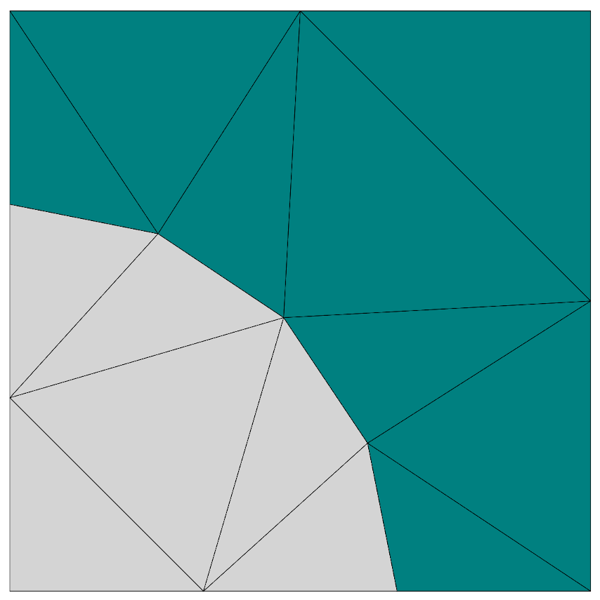 In this case the side length constraint for elements on the edge of the circle has been set to 1, equal to the circle radius. This is a coarse mesh constraints and the curve of the circle is poorly approximated.
 We now change the side length constraint for elements on the edge of the circle to be 0.1, a tenth of the circle radius. This is a finer mesh constraint and the approximation of the curved boundary becomes more accurate. This comes at the cost of an increased number of elements along the circle edge.
Curvi-Linear Elements
Continuing on from our example, instead of making the mesh finer at the boundary, we can instead specify that the circle quadrant should use curvilinear elements.
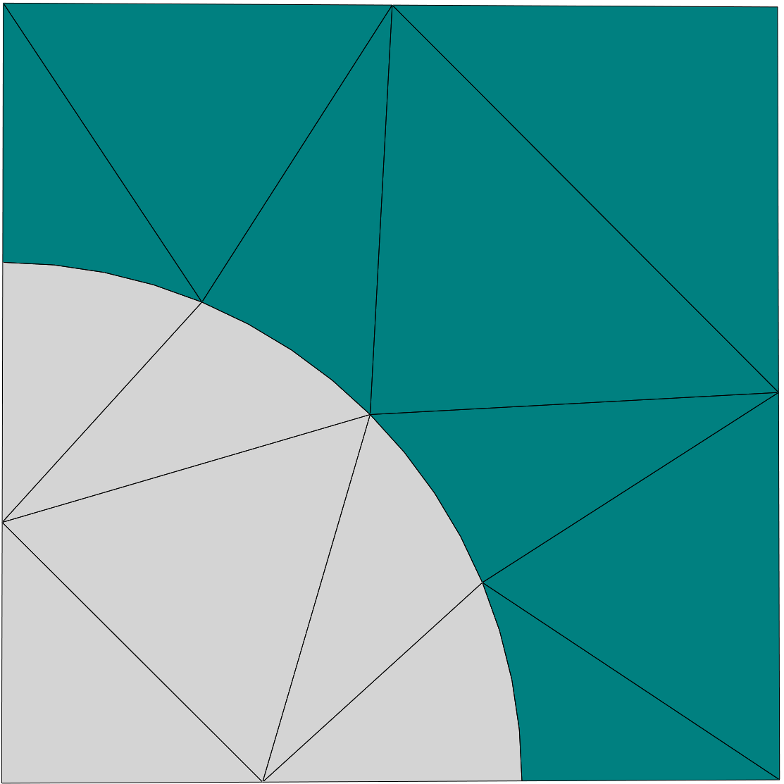 In this case the side length constraint for elements on the edge of the circle has been set to 1., the same as in our first example. Here we have specified a curvilinear degree of 2 for elements belonging to the circle. In doing so, the exterior boundary edges of the circle sector become curved. This allows the circle boundary to be well approximated with few elements.
Mathematics of Curvilinear Elements
In this part we take a brief look at the mathematical underpinnings of employing curvilinear elements. For a more complete discussion we refer to the following literature:
- I. Ergatoudis, B.M. Irons, O.C. Zienkiewicz, Curved, isoparametric, “quadrilateral” elements for finite element analysis, International Journal of Solids and Structures, 4(1), pp. 31-42, (1968)
- M. Plock, Numerical analysis of plasmonic nano-structures using the discontinuous Galerkin time-domain method on curvilinear elements, Masters Thesis, Humbolt University Berlin, (2020)
Furthermore, the figures shown in this section are reproduced with permission from the Thesis of M. Plock. Since we've been looking at triangular meshes in the post, we will continue to consider triangular mesh elements. The same considerations will apply to other element types such as quadrilateral, tetrahedral, prismal, etc.
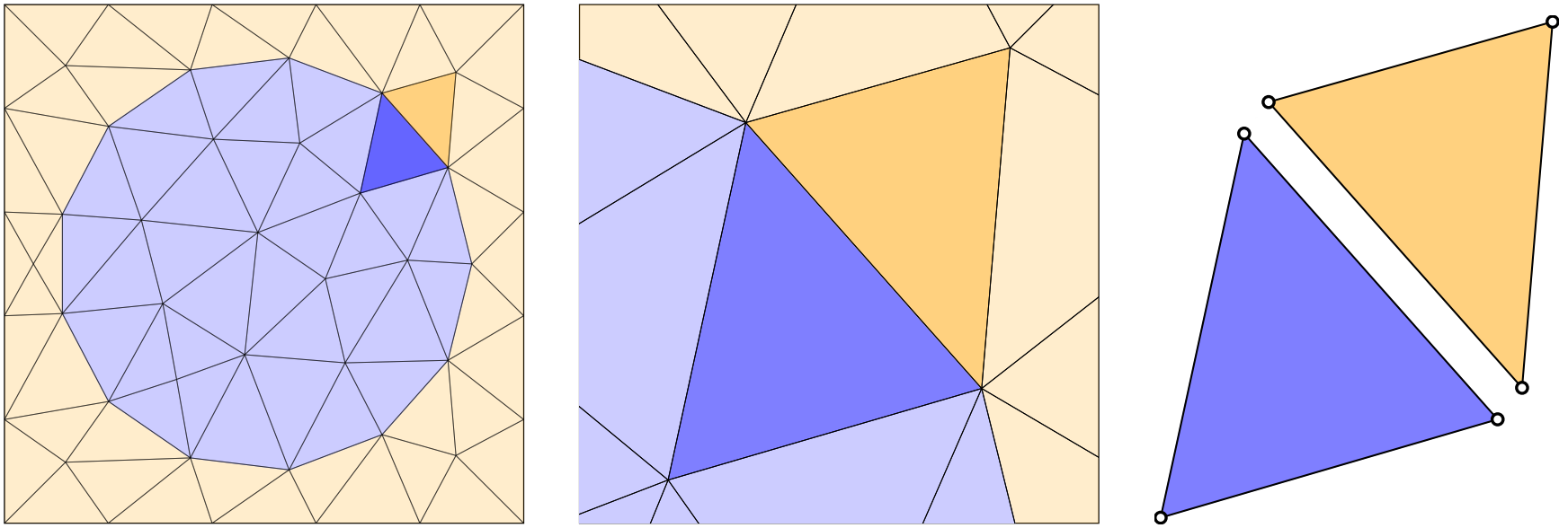 The spherical geometry is coarsely approximated via linear elements. Focusing on one of the triangular edge elements, we can consider these two elements and their associated nodes (white circles) in isolation.
Consider the triangular elements which form the edge of the circular object in the above mesh. Taking a blue (interior) and orange (exterior) pair of triangular mesh elements with a common boundary, it can be seen that each of these two elements is completely described via their three corner nodes. This is because the boundaries between the nodes are straight lines (i.e. linear) we only required a start and end point to describe each of these edges.
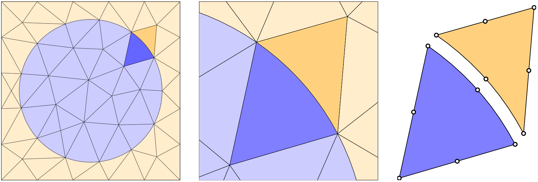 The spherical geometry is much better approximated via curvilinear elements. Focusing on one of the same two triangular edge elements, we recognize they now share a curved boundary. The origin of the curved boundary becomes clearer when we also plot their associated nodes (white circles). By also having nodes in the center of each triangular edge element, it allows for the edges to describe in this case a polynomial curve with degree two.
We now move to the example of triangular elements with curved edges shown in the circular object in the above mesh. Again, taking a blue (interior) and orange (exterior) pair of triangular mesh elements with a common boundary, it can be seen that each of these two elements is completely described via their three corner nodes and the one edge node on the boundary. This is because the curved boundary is a polynomial of second order (i.e. quadratic) which requires at least three independent points to describe. The two other straight edges have also been depicted using three nodes per edge, even though the edges are linear. This is because we need the triangles to have the same number of nodes along each edge (more on that below), but of course, a linear edge can also be described using three or more points.
This basic idea can be taken further by increasing the number of edge nodes of the triangular elements and using higher order polynomials. Indeed, we can generalize the total number of mesh nodes $N$ required for triangular meshes of a given polynomial order $m$ as:
$$ N = \frac{1}{2}(m+1)(m+2)$$Previous blog posts have covered the concept of reference elements. In performing finite element simulations, Maxwell's equations are typically solved on a reference element and then mapped onto the real physical elements used in the simulations. The reference element is typically on the unit interval,
$$ D = \{\vec{r}=(r,s)|0\leq r, s \leq 1, r+s \leq 1\}$$This mapping needs to, at a minimum, conserve the number and relative ordering of nodes along the exterior of the triangle. Furthermore we need a mapping from the reference element $D$ to the physical element $D^{k}$:
$$ \vec{\Phi}(\vec{r}) : D \rightarrow D^{(k)}, \vec{r}\mapsto\vec{x} = \vec{\Phi}^{(k)}(\vec{r}) $$In general this mapping function is a polynomial in $r$ ans $s$:
$$ \vec{x} = \vec{\Phi}^{(k)}(\vec{r}) = \sum_{0\leq i,j\leq m} \tilde{\mathbf{a}}_{ij} r^{i}s^{j}$$with $m$ being the order of the mapping and the $\tilde{a}_{ij}$ being vector valued expansion coefficients. For $m = 1$ we retain the standard linear elements with $m \geq 2$ giving higher order meshes.
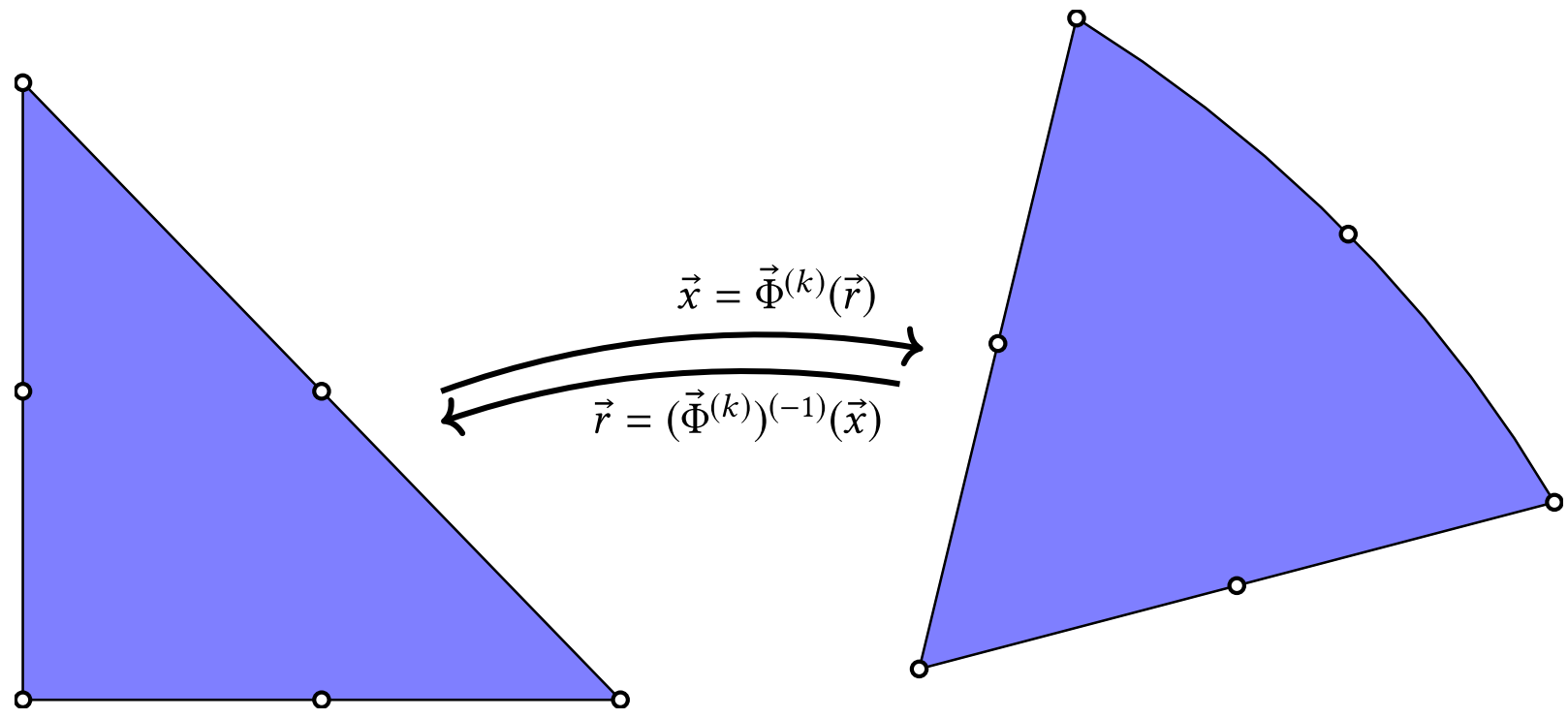 In order to be able to use the curviliear elements, we need to be able to compute the transformation from the reference triangle to the one with a curved edge. Note that both triangles have the same number of corner and edge nodes.
In order to make the concept of the transformation functions a little more concrete, we show examples of the general form of a linear,
$$ \vec{x} = \vec{\Phi}^{(k)}(\vec{r}) = \tilde{\mathbf{a}}_{0} +\tilde{\mathbf{a}}_{1}r + \tilde{\mathbf{a}}_{2}s$$,
and second order,
$$ \vec{x} = \vec{\Phi}^{(k)}(\vec{r}) = \tilde{\mathbf{a}}_{0} +\tilde{\mathbf{a}}_{1}r + \tilde{\mathbf{a}}_{2}s + \tilde{\mathbf{a}}_{3}r^{2} + \tilde{\mathbf{a}}_{4}rs + \tilde{\mathbf{a}}_{5}s^{2}$$,
transformation function. To complete the description of the curvilinear elements, we need to compute the actual coefficients $\tilde{\mathbf{a}}$. To do this we start by defining a vector $\vec{r}_{n} = (r_{n}, s_{n})$, which describes the $n$-th node on the reference element. Now we construct an $N \times N$ matrix which we will call $\mathbf{V}$, the Vandermonde matrix, using the positional vectors:
$$ \mathbf{V} = \left( \begin{array}{ccccc} r^{0}_{0}s^{0}_{0} & r^{1}_{0}s^{0}_{0} & r^{0}_{0}s^{1}_{0} & r^{2}_{0}s^{0}_{0} & \cdots\\ r^{0}_{1}s^{0}_{1} & r^{1}_{1}s^{0}_{1} & r^{0}_{1}s^{1}_{1} & r^{2}_{1}s^{0}_{1} & \cdots \\ r^{0}_{2}s^{0}_{2} & r^{1}_{2}s^{0}_{2} & r^{0}_{2}s^{1}_{2} & r^{2}_{2}s^{0}_{2} & \cdots \\ \vdots & \vdots &\vdots &\vdots & \ddots \\ \end{array}\right) $$,
With this matrix in hand, we go on to define two further vectors. Firstly, a vector made from the mesh node positions on the physical element $D^{k}$,
$$ \mathbf{x}^{(k)} = \left( \left( \mathbf{\vec{x}}^{(k)}_{0} \right)^{T}, \left( \mathbf{\vec{x}}^{(k)}_{1} \right)^{T}, \cdots \right)^{T}.$$Followed by a vector made up of the unknown expansion coefficients,
$$ \mathbf{\tilde{a}} = \left( \left( \mathbf{\tilde{a}}^{T}_{0} \right)^{T}, \left( \mathbf{\tilde{a}}^{T}_{1} \right)^{T}, \cdots \right)^{T}.$$Due to the construction of $\mathbf{V}$ it holds that,
$$ \mathbf{x}^{(k)} = \mathbf{V}\mathbf{\tilde{a}}.$$Due to the Invertibility of the Vandermonde matrix, we can obtain the unknown expansion coefficients by inverting the matrix $\mathbf{V}$,
$$ \mathbf{\tilde{a}} = \mathbf{V}^{-1}\mathbf{x}^{(k)}.$$With this final step, the mapping $\vec{\Phi}^{(k)}(\mathbf{\vec{r}})$ and inverse mapping $\left(\vec{\Phi}^{(k)}\right)^{-1}(\mathbf{\vec{x}})$ are completely specified.
Convergence of Curvilinear Elements
We've covered the basic idea of curvilinear elements and their mathematical underpinnings, now it's time to finally have a look at the numbers: what can curvilinear elements do for us?
In order to examine the advantages of curvilinear elements, we look at the scattering of light from an infinite cylinder with a circular cross section. The cylinder has the same permittivity as silver and the surrounding material is air. The wavelength of the incident light is 347 nm and the radius of the circular cross section is 50 nm. These parameters have been chosen such that a plasmonic resonance is present (for plane polarized light).
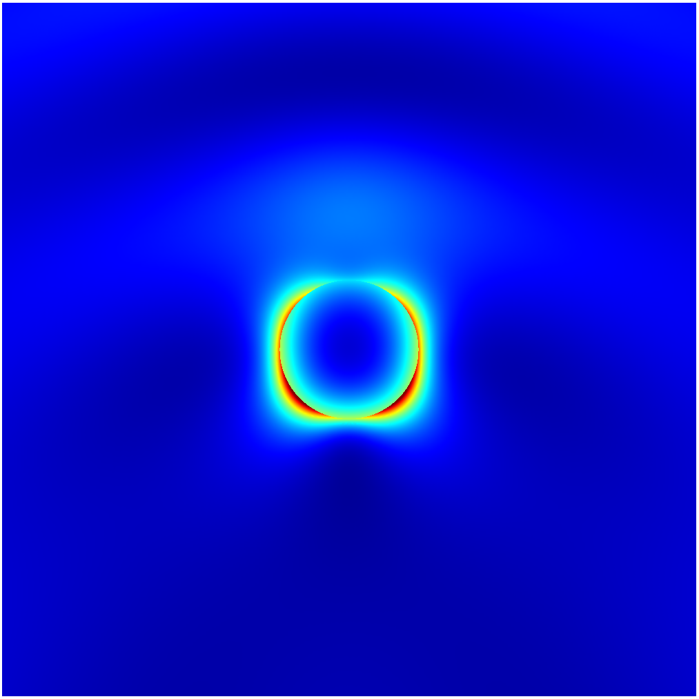 The electric field intensity is strongly localized to the surface of the circular scatterer. Thus our goal will be to balance the two sources of error, namely the error in our description of the geometry and our error in the description of the electric field solution.
In order to compare the accuracy of different field solutions, we compare the normalized scattering cross section $Q_{sca}$ of the infinite cylinder, which can also be calculated analytically. We compare four different refinement strategies for reducing the relative error of our numerically determined values of $Q_{sca}$ compared to the analytical value. In order to compare different strategies, we plot all strategies as a function of the number of numerical unknowns used to solve the system matrix. More unknowns means more time taken to complete the simulation and more memory required. The goal is to choose numerical settings to obtain an acceptably small error for the fewest number of unknowns. The convergence of the error and four of the meshes used are shown in the following figure.
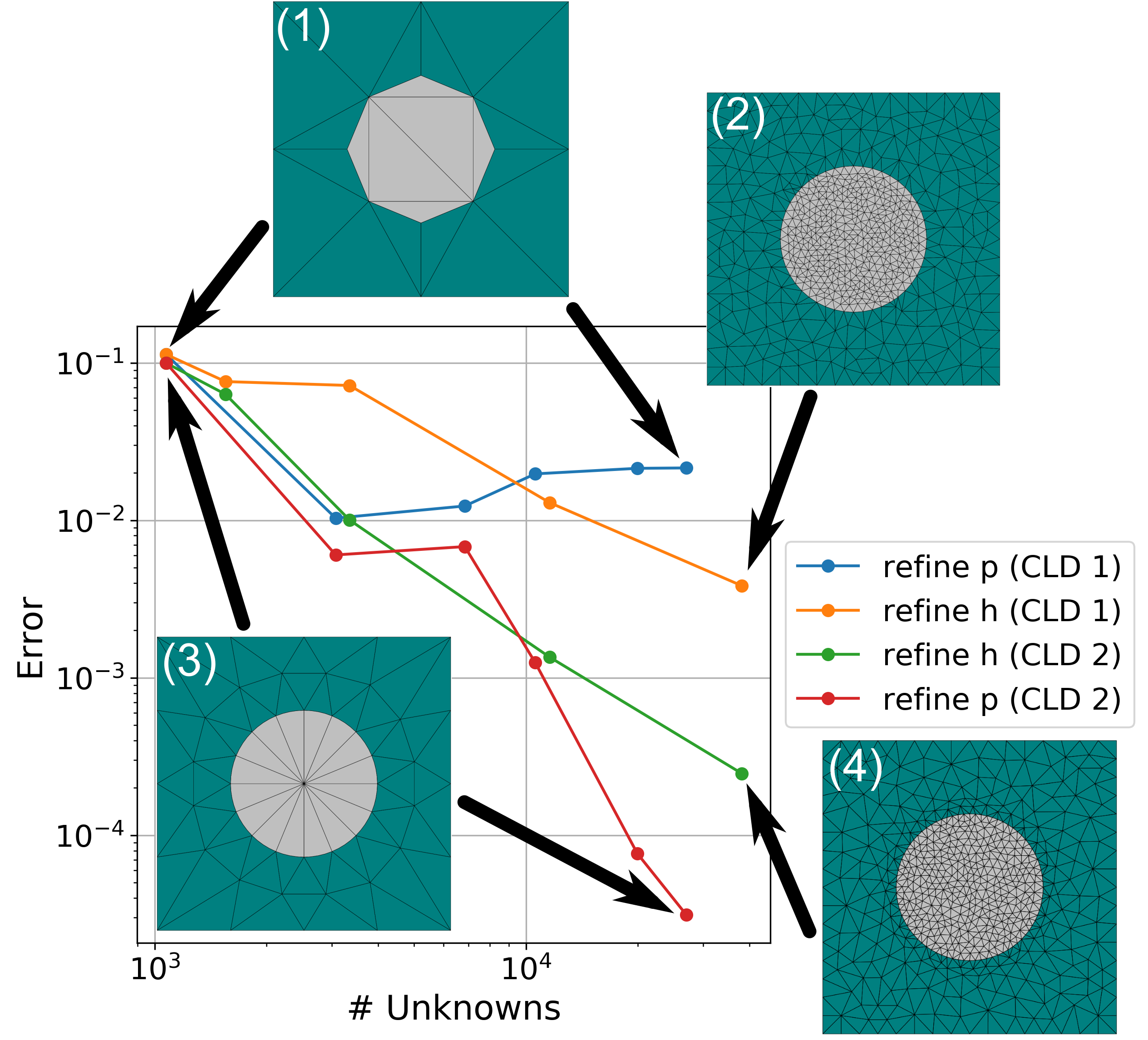 Four different refinement strategies for reducing the relative error on the scattering from a cylindrical plasmonic scatterer. The meshes used for the simulations relating to certain points in the figure are indicated.
As our starting point, we describe the geometry using a coarse mesh and use a low finite element degree for the approximation of the electric field. The course mesh (1) is shown in the top left of the image. The approximation of the circular cross section uses just six triangles, meaning that we obtain something that has straight edges and sharp corners. The curvilinear degree (CLD) of the circular cross section has been set to 1, meaning linear elements.
Increasing the finite element degree $p$ in the entire mesh (refine $p$ with (CLD 1)), the error (blue curve) reduces as $p$ increases, but eventually saturates around $2\cdot 10^{-2}$. We are unable to further reduce the error with $p$ refinements because the geometrical error is dominating.
Decreasing the mesh length $h$ in the entire mesh (refine $h$ with (CLD 1)) results in the mesh shown in the top right (2). The error (yellow curve) reduces as $h$ decreases, but at a rate slower than for the $p$ convergence. However, the error keeps decreasing, reaching error levels around $5\cdot 10^{-3}$. We are able to go below the error of the previous simulation strategy because the finer mesh has a lower geometrical error. Despite this, the error decreases slowly with the amount of unknowns used.
The third strategy presented is mesh length $h$ refinement combined with a curvilinear degree (CLD) of 2 (green curve). The coarse mesh with CLD 2 is shown in the bottom left (3), while the fine mesh with CLD 2 is shown in bottom right (4). The coarse mesh, containing few elements, is able to resolve the circular edge of the scatterer. Initially, the higher curvilinear degree does not significantly reduce the error. Remember that due to the high mesh length $h$ and a low finite element degree $p$, the solution error is also high. Once the $h$ refinement begins, an approximately order of magnitude difference between mesh refinements with CLD 1 and 2 opens up (compare the yellow and green curves). The rate of convergence (gradient of the curves) is approximately equal, the higher curvilinear degree provides a constant reduction in the error. This allows for a more accurate solution using the same number of unknowns.
The fourth and final strategy presented is increasing the finite element degree $p$ with a CLD of 2 (red curve). The mesh shown in (3) is used for all simulations. This strategy provides the lowest error for the fewest amount of unknowns. This agrees with finite element theory, which posits that below a certain geometrical error, $p$ refinements are more efficient than $h$ refinements for reducing the solution error. The curvilinear degree allows us to get below this geometrical error with fewer mesh elements, allowing the more efficient $p$ refinement to be used with a coarser mesh.
To summarize this section:
- $p$ refinements on a too coarse mesh saturates at a high error due to the geometrical error dominating.
- $h$ refinements and finite element degree 1 reduce both solution error and geometrical error, but the strategy is not extremely efficient.
- $h$ refinements and finite element degree 1 show a similar rate of convergence for curvilinear degree 1 and 2.
- Curvilinear degree 2 provides a constant reduction in the error for $h$ refinements compared to curvilinear degree 1.
- $p$ refinements on a coarse mesh with curvilinear degree 2 is the most efficient refinement strategy in this study. The $p$ refinement reduces the solution error, while the curvilinear elements reduce the geometrical error.
Conclusion
In this post we have introduced the concept of curvilinear elements, taken a look at the mathematical underpinnings of the method and presented a practical example demonstrating the power of curvilinear elements. As with many concepts in nanooptical simulations, the decision of whether to use curvilinear elements or not depends on the given problem at hand. Typically curvilinear elements can be of benefit in situations where,
- A part of the geometry is curved.
- The mesh is relatively coarse.
- The geometrical error introduced due to (1) and (2) is large enough to limit the accuracy of the simulation.
Additional Resources
- Download a free trial version of JCMsuite.
- Documentation for Curvilinear Elements in JCMsuite in 2D and in 3D.
Work cited in this article:
- I. Ergatoudis, B.M. Irons, O.C. Zienkiewicz, Curved, isoparametric, “quadrilateral” elements for finite element analysis, International Journal of Solids and Structures, 4(1), pp. 31-42, (1968)
- M. Plock, Numerical analysis of plasmonic nano-structures using the discontinuous Galerkin time-domain method on curvilinear elements, Masters Thesis, Humbolt University Berlin, (2020)
